RF/Microwave
Test Instrument

How to test Bias Tee using Vector Network Analyzer
September 21, 2018 1 min read
When I first developed a Broadband Bias Tee using our Modular RF Enclosure, I was looking for information about how to test the Bias Tee using our Vector Network Analyzer (VNA). Although it is a very simple circuits, I did not find much information on the web.
In this blog, I will summarize how to test Bias Tee using VNA. Surprisingly, some VNA has integrated Bias Tee so that it can feed DC directly through RF connector to the UUT.
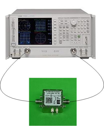
For Bias Tee, the component between two connectors is only a capacitor. In order to test the S-parameters for Bias Tee, we only need to connect VNA Port 1 and Port 2 output to the two connectors. There is no need to feed the DC Voltage on the Feed Pin. The VNA will not be able to test the DC Voltage!!! And it can damage VNA (Port 2 on right side) since we are feed DC directly on Port 2!!!
For Bias Tee, the typical S21 (Gain) is flat in its operation range. The insertion loss is about 1~2 dB. In order to make sure the DC is feed to the RF connector, we can use a multi-meter to measure the resistance between DC Port and RF connector (right side of Bias Tee). When you use the meter probe to touch the RF Connector (SMA in above image), please be very careful to not damage the Female RF connector. I strongly suggest to use another RF cable to connect to the RF connector of the Bias Tee and measure from the other end of Cable (Male Connector).
Leave a comment
Comments will be approved before showing up.
Subscribe
Sign up to get the latest on sales, new releases and more …